
THE CLOCK DRIVE
Construction
There are two types of motor available to drive a small equatorial mount, the DC motor and the stepper motor. The DC motor speed is controlled by varying the voltage applied to the motor. Driving such a motor is simple but anything that makes this voltage change, like ambient temperature and battery residual charge, will also alter rotation speed.
This is why for higher accuracy a stepper motor is the favourite choice. The speed of a stepper motor is controlled by applying electrical current to the different phases of the motor in a precisely determined sequence. The speed of the stepper is therefore not influenced by ambient temperature nor by battery voltage. I have used the aQ-Track in temperature ranging from -24°C to +25°C and the speed remained exactly the same throughout.
Programming a microcontroller chip is required to perform the desired step sequence. While this may sound like a complicated thing, thanks to the Arduino boards, this can be done by anyone owning a computer.


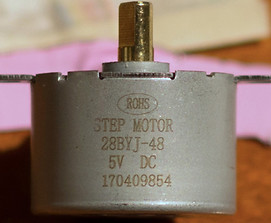
The motor driving the aQ-Track is a 28BYJ-48. It is the 5V with 16:1 gear ratio version. There is a more common 64:1 version that can also be used here. This stepper is very easy to control with an ULN2003 stepper driver. A driver is necessary because the microcontroller chip cannot handle the electrical current necessary to make the motor turn, it could fry its circuits.
The step sequence has to be programmed in the microcontroller. To do that, an Arduino Uno board is connected to a computer via a simple USB cable. The Arduino editor can be downloaded from arduino.cc and allows communication with the board. The code found here to make the stepper turn at 1.012 rpm. All 28BYJ-48 motor may not be exactly the same so you will need to check this by timing 20 to 30 revolutions to make sure you have the correct rpm. If necessary, the interval between steps can be adjusted in the code at this line: #define Interval 57965 The value "57965" is the interval between steps in microseconds. Enter a higher value if you need to slow down the rotation rate, and a lower value to speed it up.

Once the microcontroller is programmed it can be removed from the arduino, placed into a socket soldered onto a perma breadboard and placed in a project box. The picture on the left shows the final result. The voltage from the 4 AA batteries goes to a small blue "buck converter" at the top of the box. It is a XL4005E 5A DC-DC step-down module. It takes tthe 6 volts of the batteries and regulates it to a constant 5 volts signal that powers the microcontroller, the stepper driver and the stepper itself. With 5 amp capacity it can easily handle the small 200 milliamps the circuit is drawing. The project box is relatively water tight, I put hot glue on the side of the holes drilled for the switches and connector.
In after thought, a simpler way of doing this is to get an Arduino Nano board and solder it in place of the Atmega 328. This way, we can do without the buck converter by using the Nano inboard regulator on pin 30. The motor voltage doesn't need to be regulated anyway. Also, by placing the Nano usb port towards the side of the project box and drilling a hole in front of it (plugging it with some kind of rubber plug) we could upgrade or change the microcontroller programming more easily by simply connecting it to the computer.
Recommanded tools
- Soldering iron
- Third hand